 Home Page |
IPFC Summary
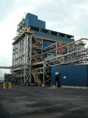
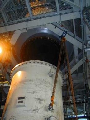
The Integrated Plasma Fuel Cell (IPFC) Process is a highly efficient process for producing hydrogen, electricity, diesel fuel, gasoline and concentrated carbon dioxide from oil, natural gas, coal or biomass. It is a process that creates these products electrochemically, without combustion. Hydrogen gas from the process is highly concentrated and can be used in petroleum refining, as a future fuel for hydrogen fuel cell powered motor vehicles, or entirely for the production of synthetic gasoline and diesel fuel. Carbon dioxide from the process is highly concentrated and can also be used for a variety of commercial applications, for example, injection into oil and natural gas wells for enhanced production, as a clothing and equipment cleaning agent, as a food grade gas for carbonation of popular bottled soft drinks like Pepsi and Coca-Cola and the production of dry ice. Excess carbon dioxide gas can also be sequestered by injection in the earth and thus avoid the release of this global warming gas to the atmosphere. The process is amenable for installation at existing refineries, industrial facilities or at the sites of existing power plants. This feature enables maximum utilization of existing oil, gas and coal infrastructure. Electricity from the process can supply industrial and refinery requirements or can be sold on the market. The plants are expected to scale from tens of kilowatts to hundreds of megawatts. How the IPFC Process WorksThe basic IPFC process is made possible by integrating two technologies, the Hydrogen Plasma Black Reactor and the Molten Carbonate Direct Carbon Fuel Cell. Diesel fuel and gasoline are made using a well-known Fischer-Tropsch process. (See the flow sheet at the bottom of this page.) The integration of the two technologies creates an innovative chemical process for extracting the maximum amount of energy and commercial products from the fuel. Because no combustion is involved, the process minimizes the production of pollutants. Process OperationsIn the basic IPFC process, a Hydrogen Plasma Black Reactor thermally decomposes a fossil fuel feed stock to elemental carbon, hydrogen, carbon monoxide and a reduced amount of pollution products. High temperature hydrogen plasma is used to crack the fuel into its elemental components. The elemental carbon is then captured in a molten carbonate working fluid and transferred to the Direct Carbon Fuel Cell, wherein the elemental carbon is electrochemically consumed to produce electrical power and pure carbon dioxide gas. The bulk of the electrical power is available for external sale or use. Some of the power is consumed in the process to power the electrodes in the Plasma Black Reactor. Hydrogen gases from the Hydrogen Plasma Black Reactor can be used in a Fischer-Tropsch process to produce synthetic fuels. A Water Gas Shift Reactor consumes the carbon monoxide from the Hydrogen Plasma Black Reactor to produce concentrated streams of hydrogen and carbon dioxide. The attractiveness of the IPFC Process is that it can be configured to produce only electricity or to produce some combination of electricity, hydrogen and liquid motor fuels. Preliminary economic analyses based on the projected capital cost of the Direct Carbon Fuel Cell achieves considerable savings in power production and hydrogen costs compared to conventional and combined-cycle power plants. The flexibility of co-products creates an economically attractive power generation, hydrogen-production, and synthetic transportation fuels. The IPFC process can achieve much higher thermal efficiencies for producing electricity ranging from a low of 70% to a high of 92%. Values vary depending upon the type of fuel, the amount of hydrogen produced in relation to the amount of electricity, and the heating value of the fuel. Typically, lower thermal efficiencies are for biomass (wood) fuel, and the highest thermal efficiency value (92%) is obtained using petroleum fuel. The IPFC Empowers a Hydrogen EconomyThere are two substantial roadblocks to a hydrogen economy. These are: producing hydrogen from fossil fuels may be more expensive than directly using the fossil fuel; and, equally important, producing hydrogen from fossil fuels may cause more pollution than directly using the fossil fuel. The IPFC process removes these roadblocks and produces hydrogen from fossil fuels more economically and with much less pollution than if the fuel were used directly or in combined cycle plants. Using hydrogen in a Syngas process produces gasoline and diesel fuel, which eliminates hydrogen storage and pipeline requirements. Hydrogen Plasma Black ReactorThe Hydrogen Plasma Black Reactor was developed by Kvaerner (now Aker Kvaerner) and was used on an industrial scale to produce carbon black for tires. See photographs on this page of Karbomont Montreal Hydrogen Plasma Black Reactor plant and a bottom view of one of the two reactors. The Karbomont plant, now decommissioned, had a design capacity to produce hydrogen at the rate of 2.5 Billion Cubic Feet/per year and 20,000 tonnes per year of carbon black from two reactors. 20,000 tonnes of carbon black per year at 1.5 kw(e) per house would provide electricity for 13,000 homes.
An Operational Direct Carbon Fuel CellIn the Integrated Plasma Fuel Cell (IPFC) process, the Direct Carbon
Fuel Cell operates using a recirculating molten carbonate electrolyte as a
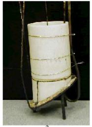
carbon transfer medium. Experience using molten carbonate electrolytes in megawatt-scale hydrogen fuel cells is directly applicable to this process. The laboratory scale Direct Carbon Fuel Cell (shown in the following photograph) has been operated at the U.S. Department of Energy's Lawrence Livermore National Laboratory.
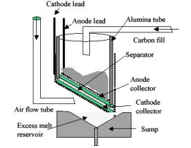
The photo shows a laboratory cell of 60 square centimeters. The electrode assembly is placed at an angle of 45 degrees from horizontal. The tilted orientation helps drain excess electrolyte from the cell from the cell that might otherwise collect in depressions in a horizontal electrode and shut off access of oxygen to reactive cathode sites. It also prevents flooding of the metallic cathode and corrosion to Ni2CO3 during startup that would prevent development of a compact, defect-free film with the desired catalysis. Finally, the tilt allows the electrolyte to be exchanged between the separator, electrodes, and an adjacent reservoir, to maintain sufficient electrolyte during progressive consumption of the carbon inventory.
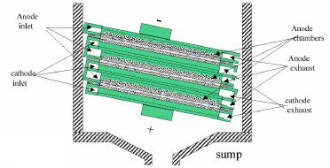
The graphic at the right is a schematic of a cell tilted to allow exchange of melt between the cell and an underlying sump, to regulate wetting of the carbon. One conceptual approach to an industrial-scale Direct Carbon Fuel Cell suggested by the lab-scale design is shown in the following schematic of a cell cross-section which would maintain orientation in a bipolar stack of rectangular cells and provide for a flow of carbon saturated molten salt.
The electrode assembly is placed at an angle of 5-45° from horizontal.
This tilted orientation helps drain excess electrolyte. Status of DevelopmentThe critical engineering path for building an IPFC process plant is the scaling-up of the Direct Carbon Fuel Cell and the integration of the Direct Carbon Fuel Cell with the Hydrogen Plasma Black Reactor. The IPFC process is also explained in four pages of text and 3 flow sheets in a downloadable Acrobat (.pdf) document, and a 39 page slide presentation in Powerpoint format (.ppt)(~3.5 MB) or Acrobat (.pdf)(~7 MB) format. The following flow chart shows the IPFC Process with a step to produce transportation fuels: |